|
|
Ram BOP
Well control equipment are mainly applied in operation of drilling, work-over and well testing etc. to control wellhead pressure, effectively prevent the occurrence of the blowout accident and secure drilling operation.
TYPE U Ram Bop
TYPE U Ram BOP is designed and manufactured according to API Spec 16A standard and GB/T20174 Drilling and production equipment-Drill-through equipment, and is equipped with rams of various sizes.
With the best quality front ram rubber, top ram rubber and flange sealing stacks, TYPE U ram BOP can work during the extreme working condition including extremely high or low temperature and extreme chemical environment.
Features:
●The pressure-bearing components are forged, so it has better strength and impact toughness.
●Floating sealing is applied to the cylinder cover and the open/close of the cover is realized by hydraulic power, so it is quick and convenient for changing rams.
●The auxiliary oil cylinder affords a smaller volume with same function.
●The ram rubber has massive storage volume, and it adopts self-contained sealing.
●The standard configuration includes a manual locking device, which ensures the ram is closed tightly in case there is a hydraulic pressure loss.
●Both the manual and hydraulic locking device and the auxiliary oil cylinder can be installed flexibly into different positions according to customers’ requirements, and the installation positions can be changed easily.
●Ram cavity can be fitted with ram assembly of same type BOP made abroad.
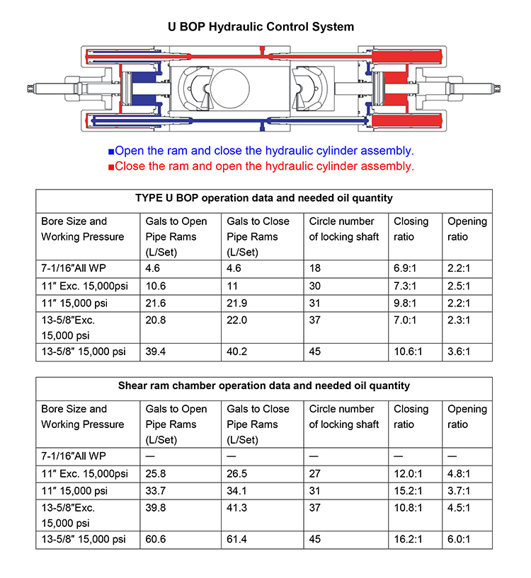
U BOP Hydraulic Control System
The U blowout preventer is designed so that hydraulic pressure opens and closes the rams and provides the means for quick ram change-out.
Ram closing pressure closes the rams. When the bonnet bolts are removed, closing pressure opens the bonnet. After the bonnet has moved to the fully extended position, the ram is clear of the body. An eyebolt can be installed in the top of each ram to lift it out of the preventer.
Ram opening pressure opens the rams. Following ram change-out, this pressure closes the bonnets. The rams are pulled outward, near the bonnets, before the bonnets begin moving toward the preventer body. This assures that the rams never obstruct the bore or interfere with the pipe in the hole. Hydraulic pressure draws the bonnets tightly against the preventer body and the bonnet bolts are reinstalled to hold the bonnets closed.
BOP Specifications
●Side outsets to 4-1/16” (7-1/16” on 26-3/4” BOPs) can be provided beneath each set of rams on either or both sides of U BOPs. Side outlets can be studded, open-face flange or clamp hub with the same pressure rating as the vertical run connections.
●Flanges conform to API standard 6A and/or 16A. Hubs conform to API 16A or applicable standards. Type 6BX flanges are standard for 10,000 and 15,000 PSI working pressure and for 5,000 PSI for 13-5/8” and larger bore BOPs.
Hydraulic control connections for operation of rams and bonnets are 1” NPT. There are two connections for each set of rams.
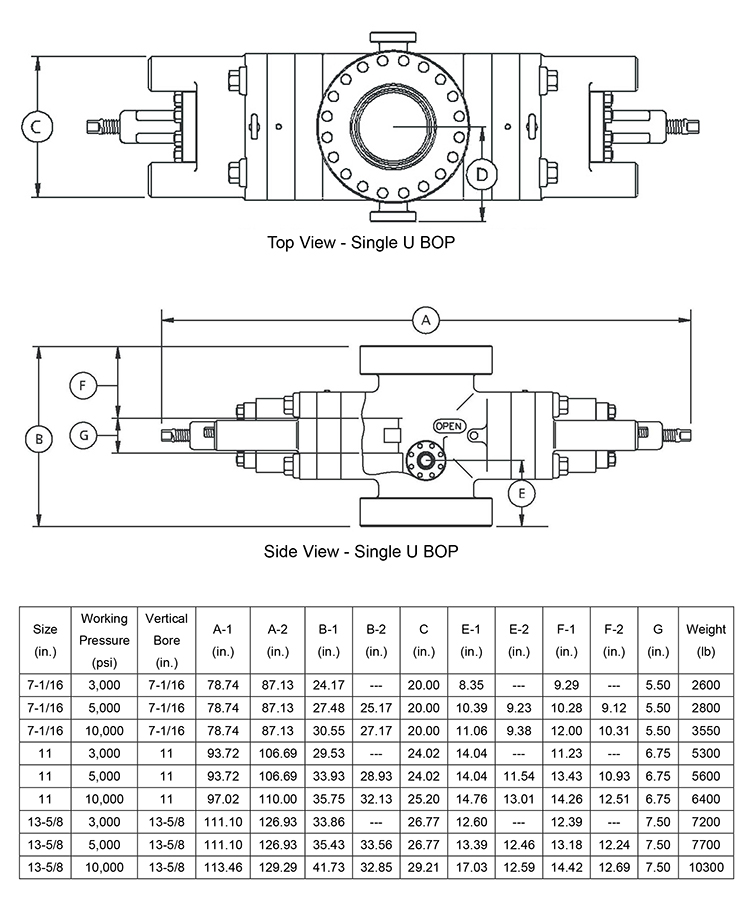
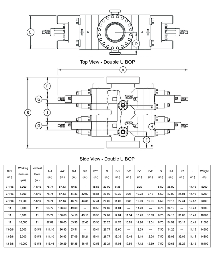
The capital letters in the following designations refer to the U BOP dimensional views and dimensional charts shown on the following pages.
A-1 Length – ram closed, locking screws locked
A-2 Length – ram opened, locking screws unlocked
B-1 Height – flanged
B-2 Height – clamp hubs
B*** Height – added height if 30″ spacing is required for double
C Width – no side outlets
D Centerline of preventer to outlet flange or hub face.
This distance is variable and must be determined per individual specifications.
E-1 Centerline of side outlet below rams to bottom flange face
E-2 Centerline of side outlet below rams to bottom hub face
F-1 Top of upper ram to top flange face
F-2 Top of upper ram to top hub face
G Height of ram
H-1 Centerline of side outlet between rams to bottom flange face
H-2 Centerline of side outlet between rams to bottom hub face
J Top of lower ram to bottom of upper ram
Note: All weights listed are based on forgings.
U BOP Single Open Faced Flange or Clamp Hub Dimensions
Note: All weights listed are based on utilizing closed die forgings.
U BOP Double Open Faced Flange or Clamp Hub Dimensions
Weights shown are for flange x flange top / bottom
Note: All weights listed are based on utilizing closed die forgings.
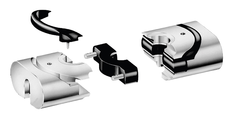
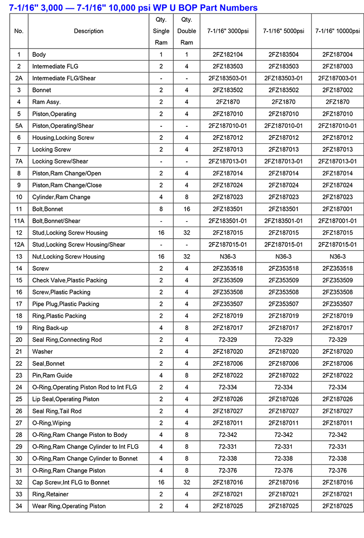
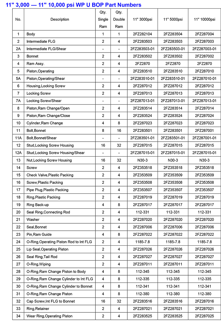
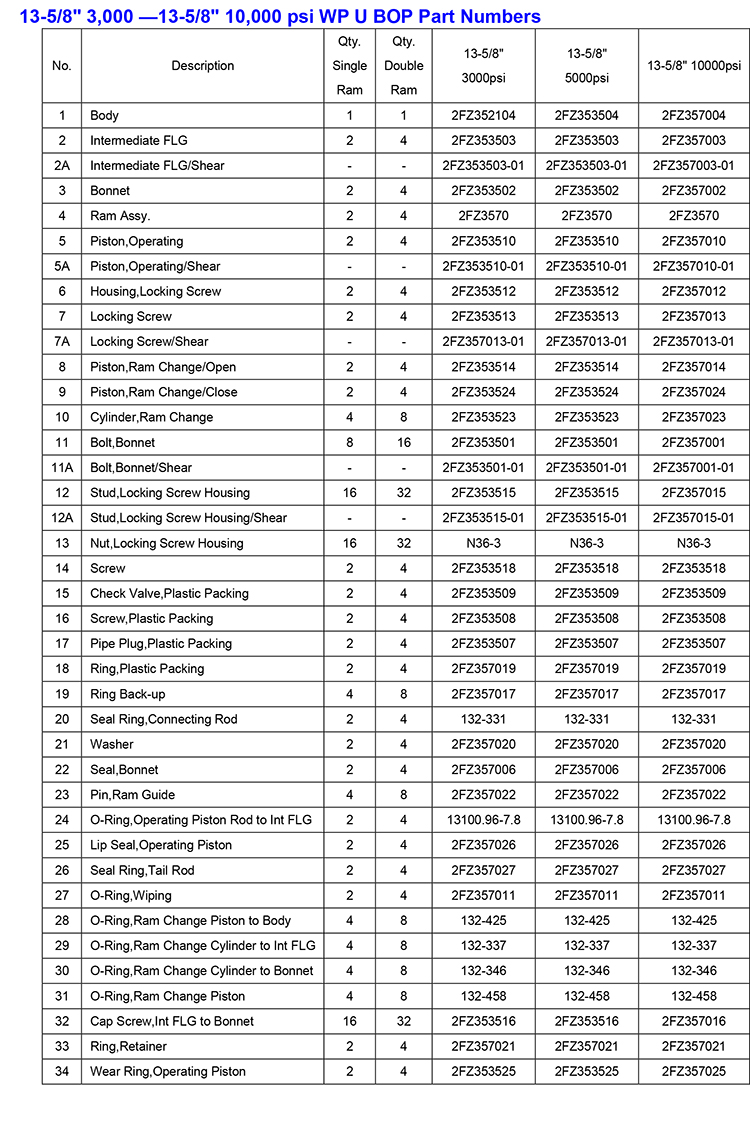
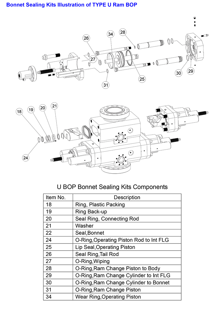
TYPE U BOP Explosion Drawing
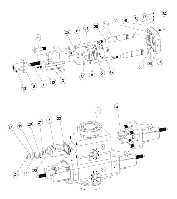
Double U BOP
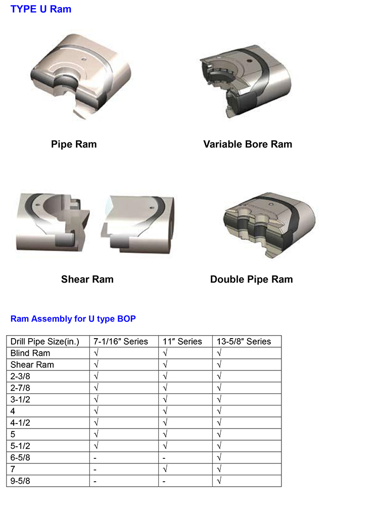
U BOP Rams
The standard “ U “ BOP pipe rams are interchangeable for the U BOP’s.
Pipe rams are available for use in U BOPs to fit all commonly used size of tubing, drill pipe, drill collar or casing within the rangs in the charts on the following pages. pipe rams include the following features:
● Pipe rams are self-feeding and incorporate a large reservoir of packer rubber to ensure a long-lasting
seal under all conditions.
●Ram packers lock into place and are not dislodged by well flow.
● All pipe rams are suitable for H2S service per NACE MR-01-75.
● Top seals are standard for all U BOP pipe rams from 7-1/16“ through 13-5/8” sizes. Packer part numbers beginning with SU indicate the lipped-plate design. Other part numbers may use standard elastomer material and reinforced plates. Verify this with your representative.